


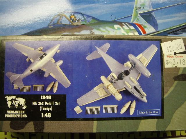
Tamiya's Me262 kit #87 with Verlinden's detail set # VP1846.
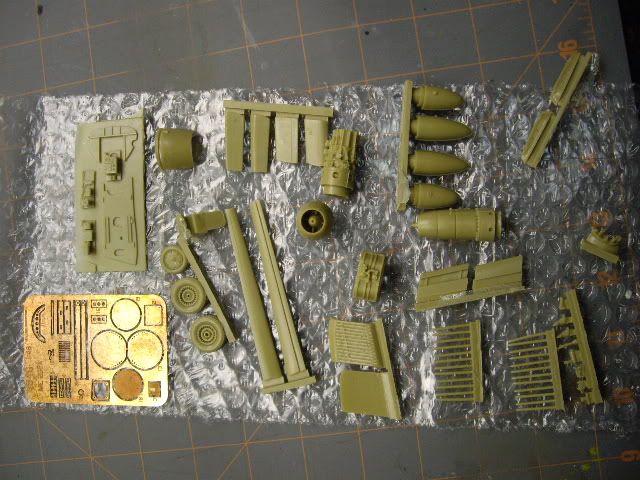
The detail set comes with slats, flaps, wheels, a complete engine, some cockpit and interior details all in resin and PE.
The resin looks to be pretty nice, but the kit doesn't seem to need much and would stand on it's own. I picked the kit up a few years ago for $10 and I got the detail set at a show for $20
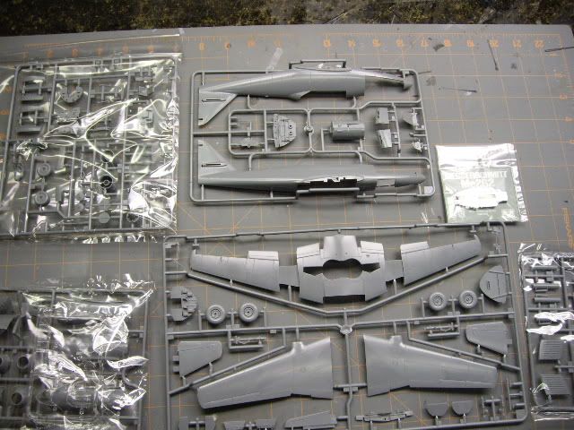
Here are some sprue shots 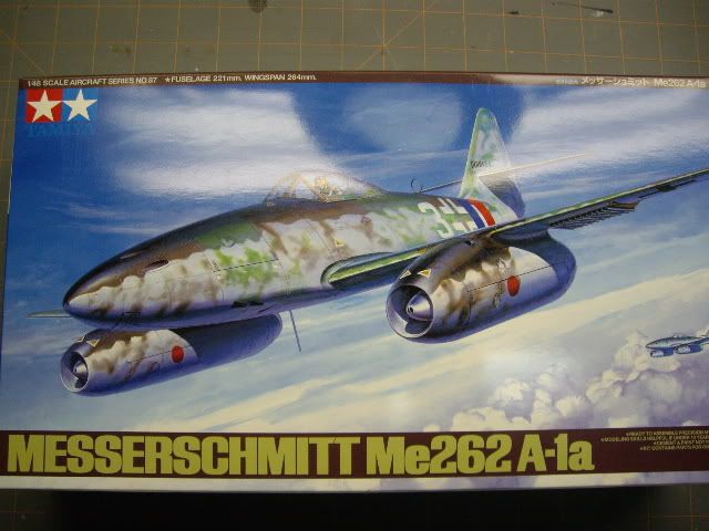
I thought this was a nice touch. A weighted front wheel bay. 
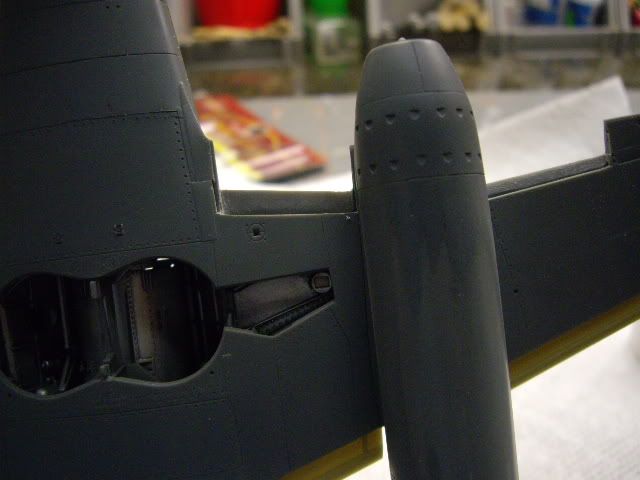
I've managed to paint the main parts of the cockpit and finished cutting out the flaps and slats. I also cut away the access panel on the starboard side. That was alot harder than I thought. Without making any slips, the opening was slightly larger than the PE part.
I noticed this before I started cutting, but didn't know what to do about it so I forged ahead. I think in the end after it's painted it will give the right effect so I'm not going to worry about it.
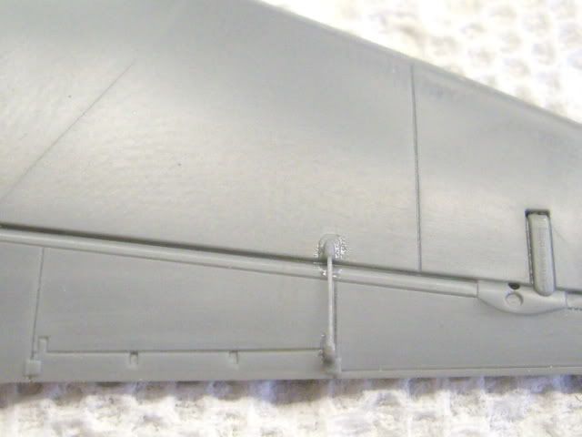
Here are the wings after I finished cutting away the surfaces. 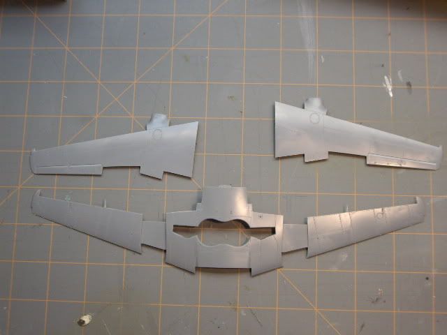
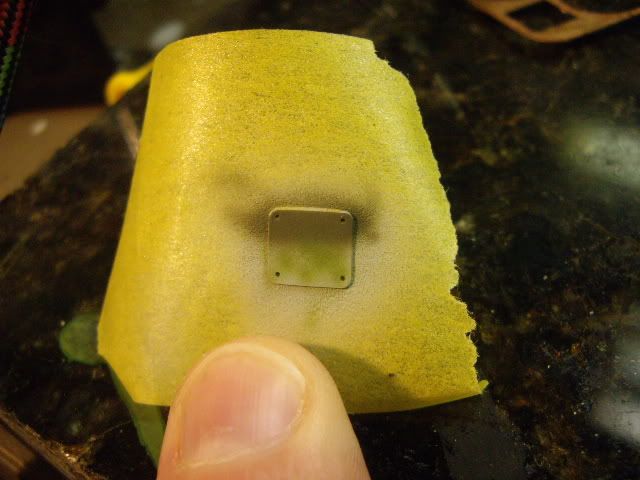
Those little points are all that was left when done. I stressed about breaking them off as I scribed. 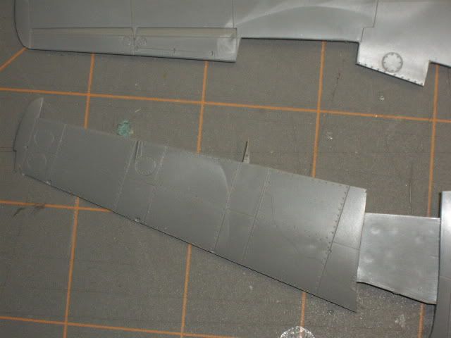 The access panel. I used styrene strip to give the plate something to sit on. It looks like the panel is out of shape, but thats how it was on the kit. I made an extra effort not to go outside the lines.
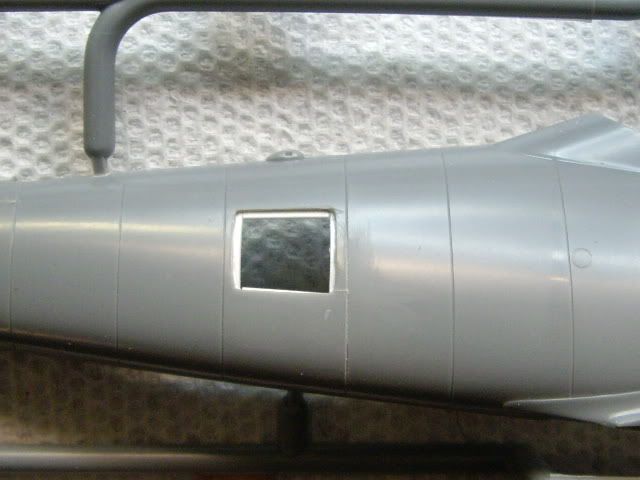

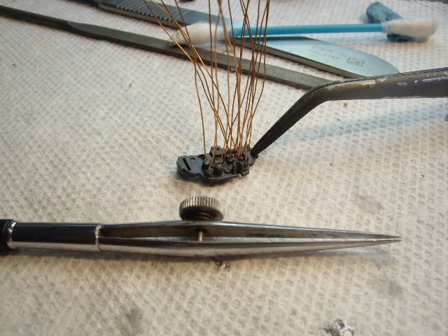
Next was on to the cockpit. I decided to wire the back of the panel. Here I've used some wire from an extension cord I botched with the weedwacker a few years ago.
I use an old artist inking pen to apply supper glue. 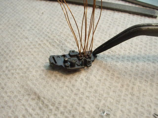
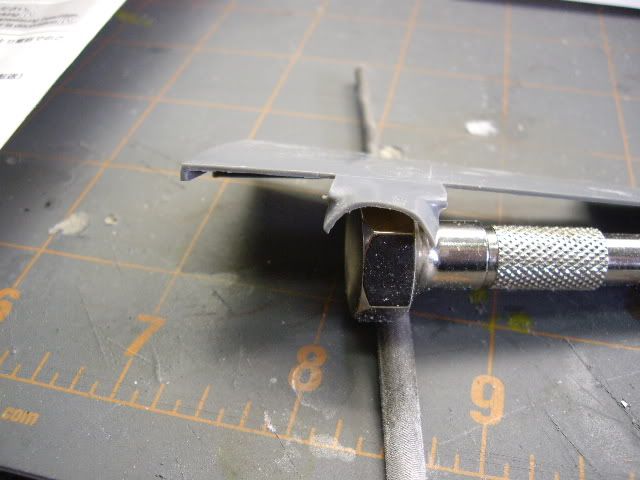
Here is the map holder. It is the only PE part in the pit. I have a Mission Models PE bending tool, which comes in handy. 
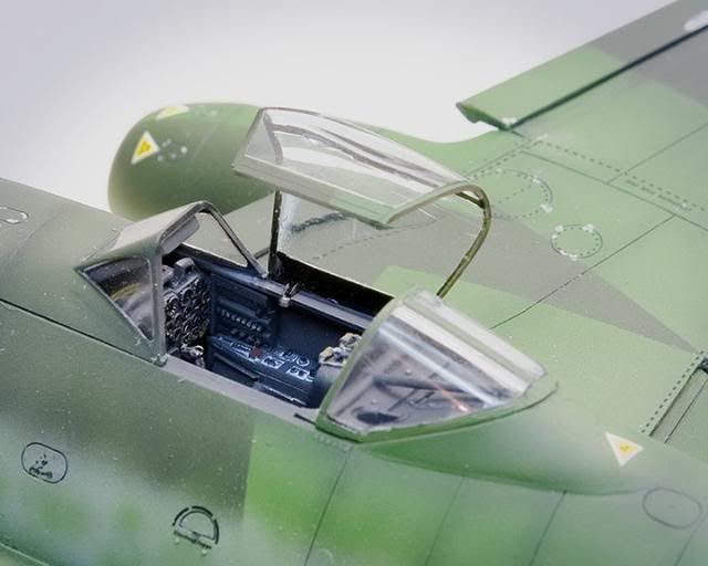
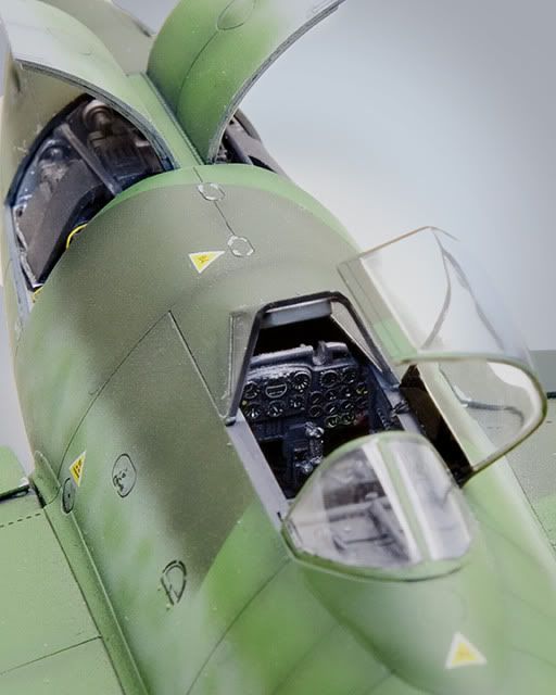
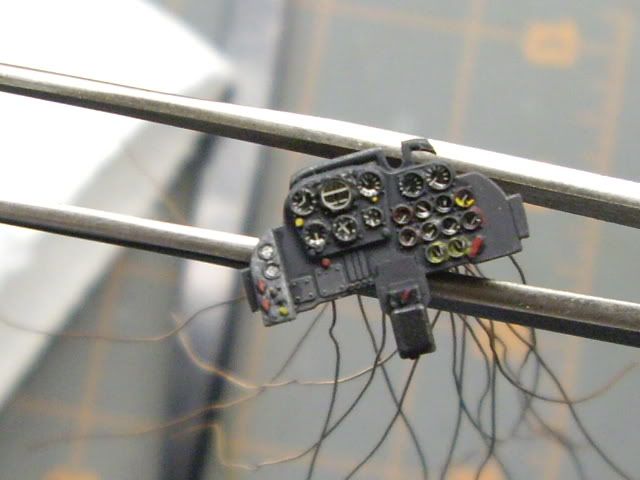
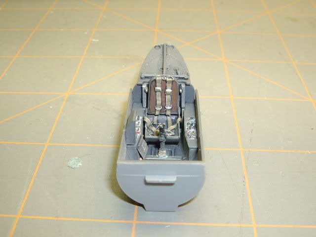
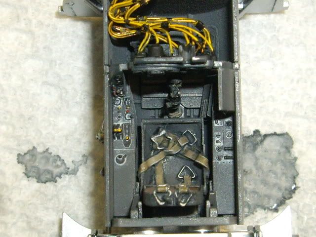
Next up are just some shots of the cockpit. I need to tie the wires up on the panel and paint them before I can glue it up. It's full of hairs and blue tac that need to be pulled.
Actually since these pictures are after the fact it's already done. Also I use these shots to see where I've messed things up painting and I've gone back and touched them up. 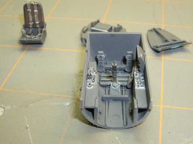

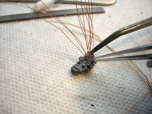
Sorted out the wire binding issue and here is what I came up with. After all was said and done I could have just painted a black line accross the wires and it would have looked just as good. I'm guessing you won't be able to see a lick of it when it's done!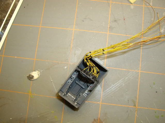
I drilled a hole through the bulkhead to route the wires into the empty cavity between the cockpit and gunbay.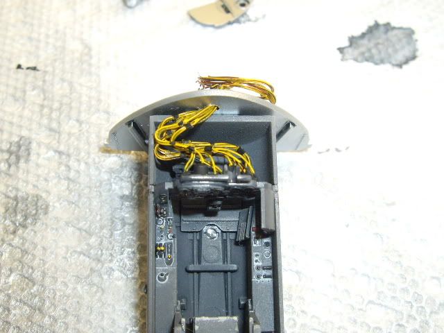
Next I moved onto the resin bits in the rear fusalage. All I did was cut them out and get them ready for painting and positioning.
I wanted to move forward with the gunbay first. 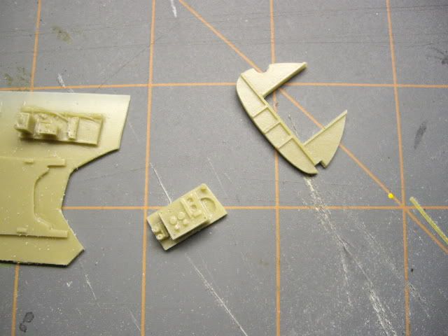
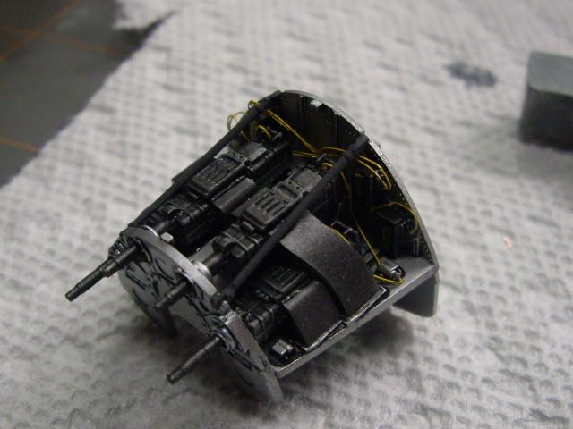
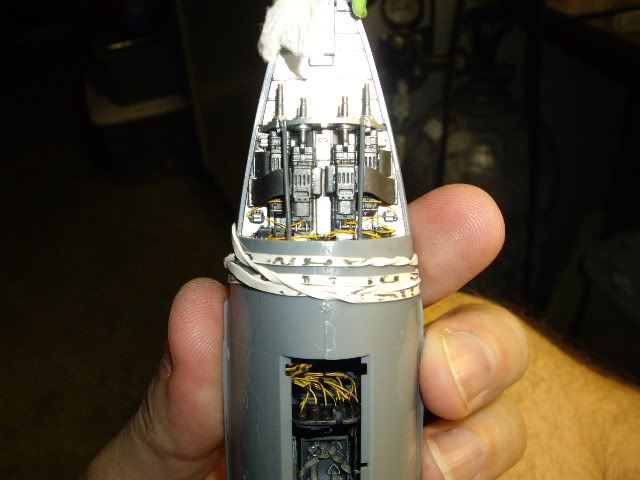
Onto the gunbay.. This was my first time using Alclad. All I can say is wow! I don't know why I put this off for so long. 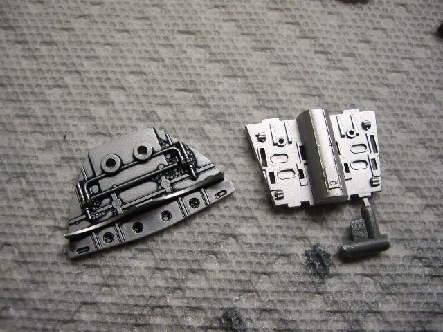
After black washing all the parts I decided to wire the gun bay as best I could. Not completely accurate, so just don't look at reference photos and who'll know. 
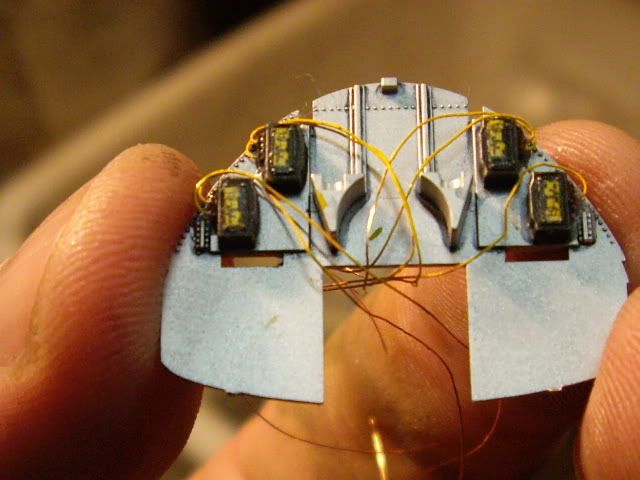
These are the completed shots of the sub assemblies. All there is to do is flat coat some things and fit the resin gunsight. I might wire that too. 
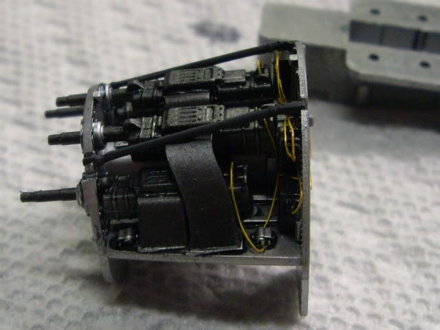

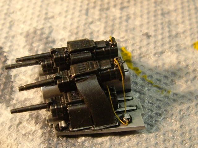
Added a few more wires to this. I got a copy of the Squadron Me262 in detail book and this helped out with some of the stuff I'd been missing.
Simple things like the fact the fuel tank was made of sealable rubber so it's black. I would have guessed it's metal. It really helped with the placement as the resin instructions are off a bit.
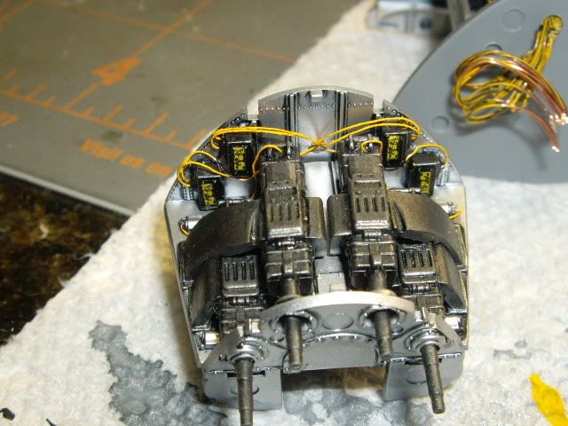
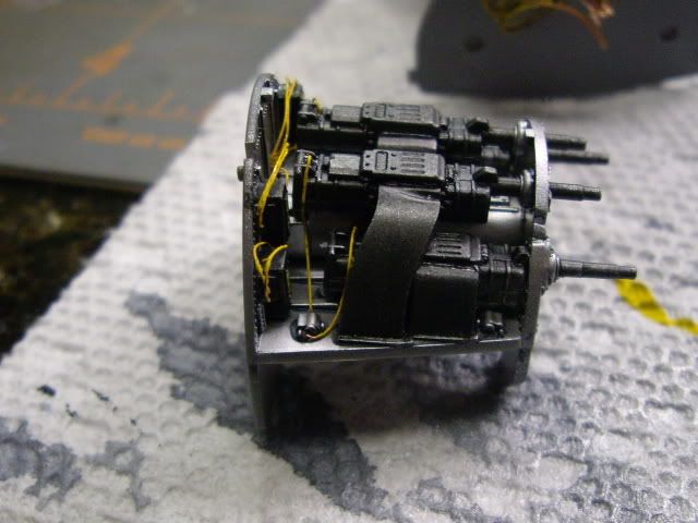
The Verlinden set is decent, but man it leaves alot to figure out. When it came to placing this stuff it references the spars in the fusalage to lay them against and gave you the angles, but you have to figure that out by looking a guessing what it means.
It would be nice if they mention things like some basic colors and a little more detail for construction as opposed to "Cut this part" What's this "Part!" I suppose it will help with the next verlinden set I do so now I'll know.
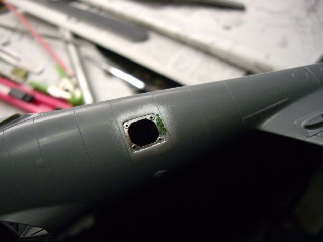
It just needs to be flat coated before I close it up now. As I suspected all of this will be viewed through a 1/4" sqaure hole. The bottom line? You can't really see any of it! 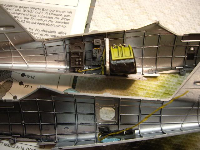
Started on with the port wing engine surgery. You have to cut out a small piece to attach to the top wing to get the PE to work right.
The verlinden instructions again failed by not letting the user know what pieces. After looking at my book for awhile I figured out what the master molder was trying to convey......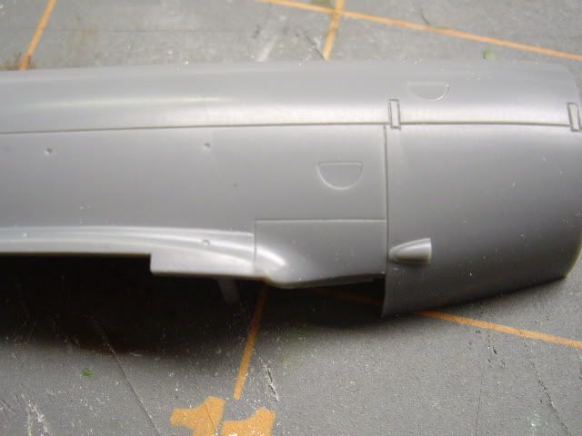
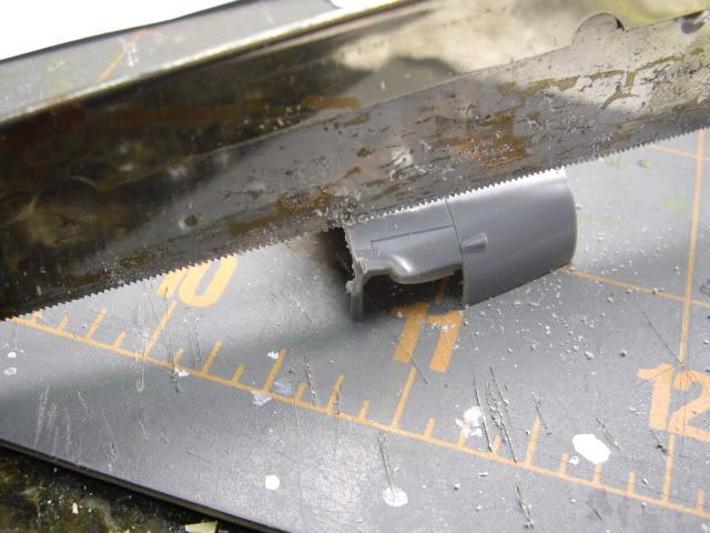

After sawing and sanding down both halves of the kits parts your left with the little pieces as shown above. Once attached and sanded it looks like this....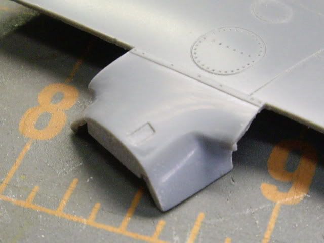

Next I cut the major engine parts out to see how they would go together. Again you will not be able to fit this together right without referneces.
The hard part is that they did not represent every box or hose so you have to figure out which ones they did to orientate it right. After figuring it out, I set it asside until I get to the stage where it is needed. 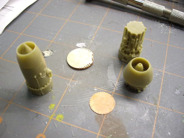
Next was on to fitting the interior into the fusalage to bring the halves together. The fit of this kit is great, but because I added some things and it has the metal weight for the nose gear, it needs to be treated as if it had a resin tub in it.
Everything fits so precise into its place that if you mis align something, it becomes a domeno effect down the road. 
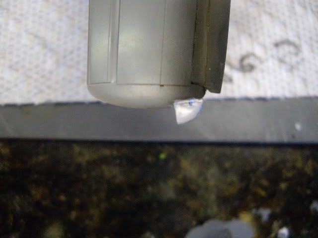
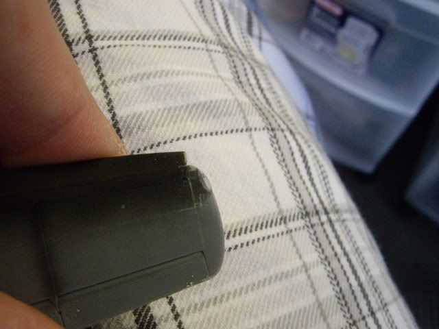
So everything was going pretty well. The above pics were prior to glue and it showed everything was gonna be fine. I started gluing the gun bay from underneath, and, well, my finger was a little to close to the edge and you know what happens.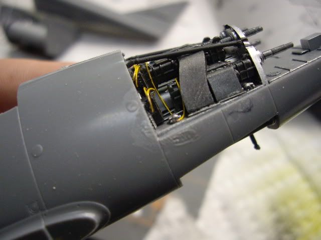
A little sanding and a hit with the mico mesh and it was fixed.
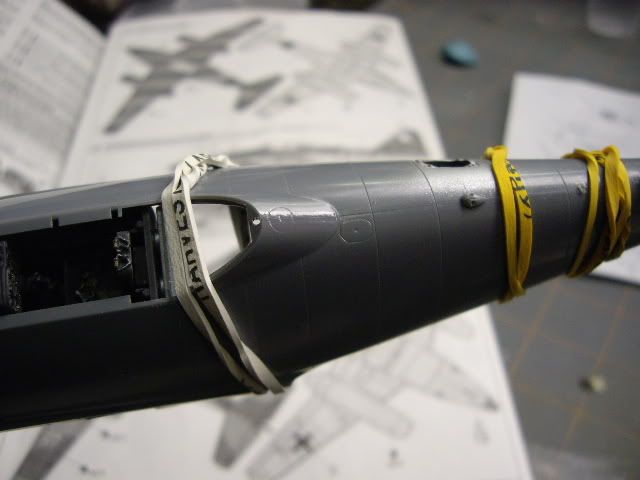
So this is where the trouble starts. I followed the kit instructions which will have you install the nose gear in the begining. The way the support is designed is it drops in from the top and there is no way to install it after its closed. so I went ahead and did it.
I thought I would be smart and "cut" the rubber bands off so I wouldn't ahve to avoid the ger leg. That worked great until I cut the last band and dropped it. So I go looking for the end of the gear leg on my garage floor and it is no where to be seen.
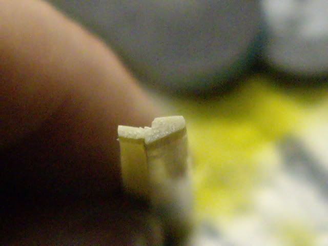
It broke in a good spot, but what to do. I decided to make a new one. Attempts failed at laminating sheets of styrene so I used one of the resin pour stubs. 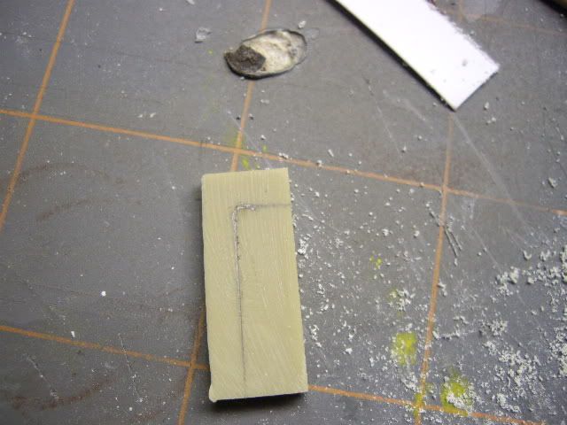
After sanding and grinding I drilled and pinned a tube to the top. Once attached I dipped the resin in boiling water to bend it in a little bit. I should have built this in when I pre shapped it, but becuase I didn't have a scale drawing, it didnt become aparent until I put the wheel up to it.
This is what I came up with. I added a piece of wire and sanded it down a bit to simulate the weld bead on the side. I just have to add some bits to the back that I see in the references. I just hope it holds when I size and pin it to the part that didn't break off the plane. 


|
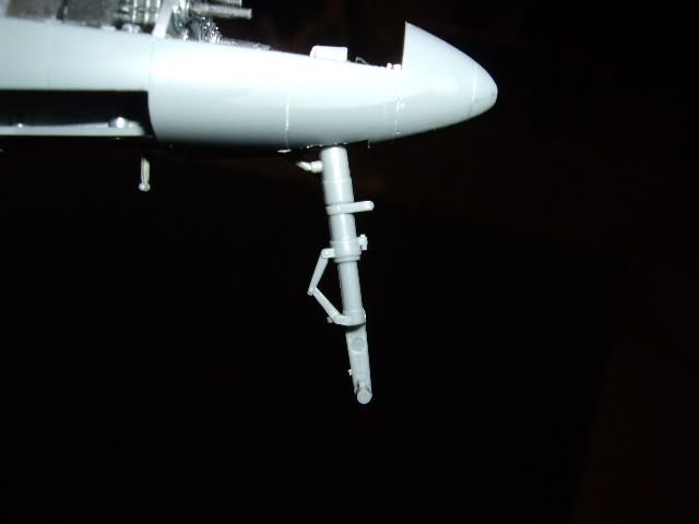
I was looking at the sprues and noticed Tamiya included a nose wheel for the earlier variant. This one has the scissors on it, which the later ones didn't. Easy modification. I carved the old one out and put this one in. This time it's not glued and I'll I'll attach later. Just have to mask around the actuators now... |
|||
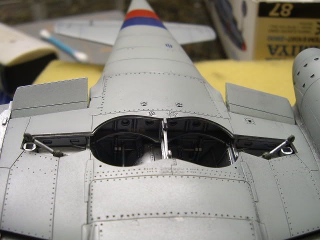
I've masked and placed the windscreen. Nice little touch by Tamiya as the part fits into natural panel lines. No filling and sanding to fair it in at the glass.
I put the main gear bracing in...simple fit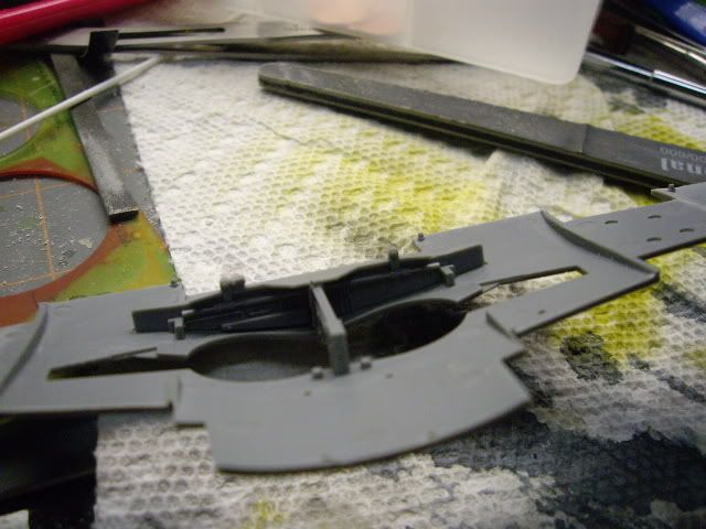
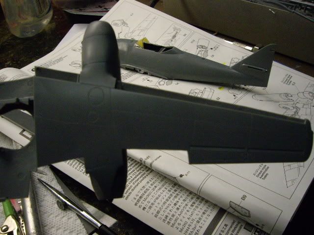
completed the starboard engine. I had to do a little filling hear and there to fair the parts into the wing, but nothing major...
I've sprayed the joins to check how they turned out. A little touch up here and there is all that is needed..
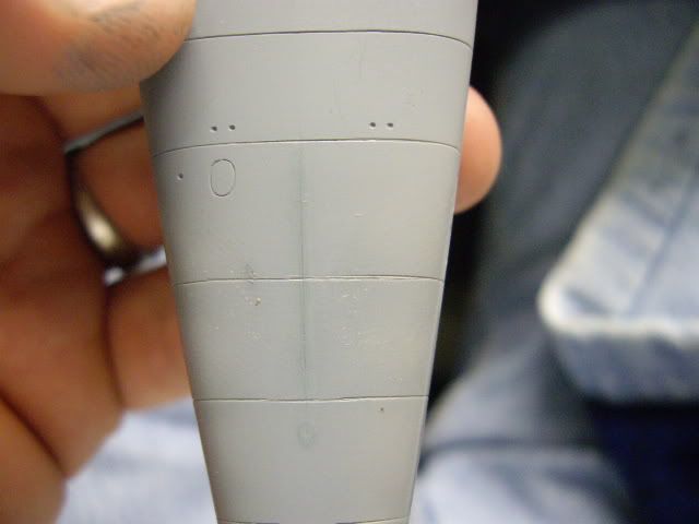
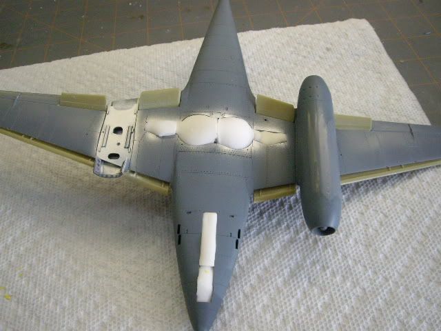
Next I rescribed the access panels on the nose and put the seam back in. 
A touch of extra thin smoothed the scribes out. 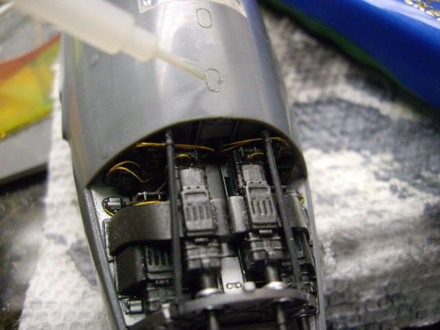
After a quick hit with some paint I decided to fill a couple spots where needed.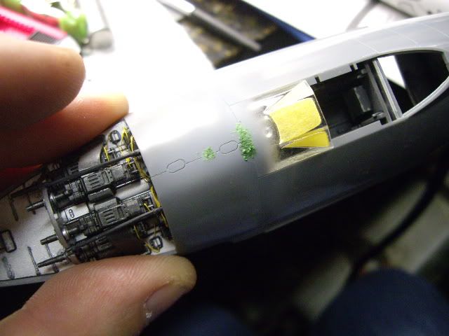
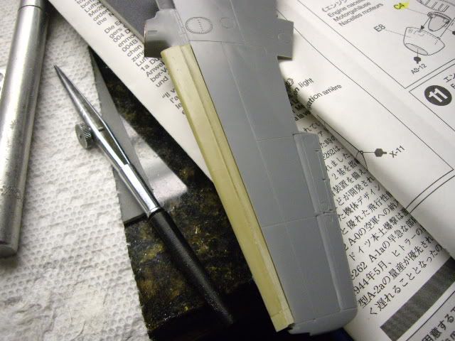
Next I moved on to the leading edge slats. I found the resin was about an eighth of an inch too short.
I had to graph a piece of pour stub on the end of each and sand them to shape to get the right fit.
All I used was some CA and sanding sticks. To get the sharp recess, I used the edge of a needle file to cut it in. 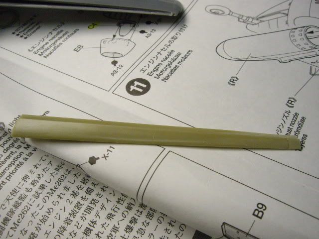

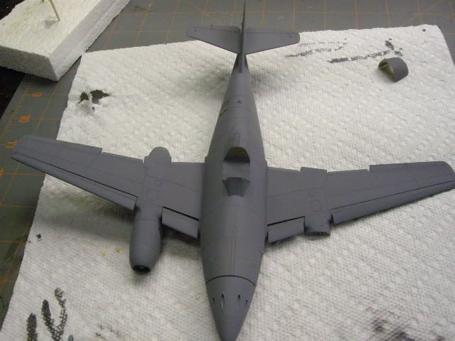
Next it will be to mount the wings to the fuselage. Test fitting shows the top joint will be pretty good. The bottom has some over sized gaps, which again, all fall on panel lines, but would be pretty large in scale.
I've tended not to worry so much about making the seams perfect on this one. All of the references I read about these planes were that they were thrown together. I'm trying to find a compromise to this.....
A rubber band was all I needed to get the important top wing roots to sit flush. When I glued the wing halfs togetether, I left the leading and trainling edges, what's left of them anyways, loose so I could make adjustments before the glue set.
This proved to be a smart move, as I was able to lift the edge up a bit to sit flush....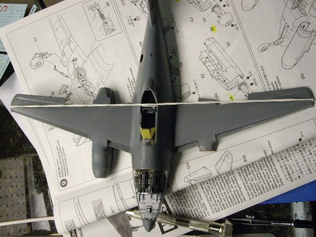
A quick shot of paint and I noticed some seams out of shape. So on with the CA to fill em in. The rear fuselage joint was from a thin glue seam. It wasn't there before, but after bumping the kit around, the seam fell out of allignment.
I've had this problem all over the fuselage, seams get sanded out, then re appear the next day. Not enought glue I suppose, but I never had this problem before until I read another members post about the same problem. 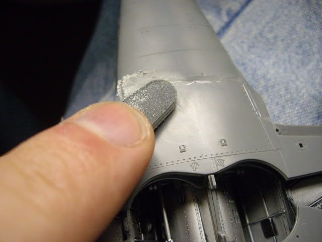

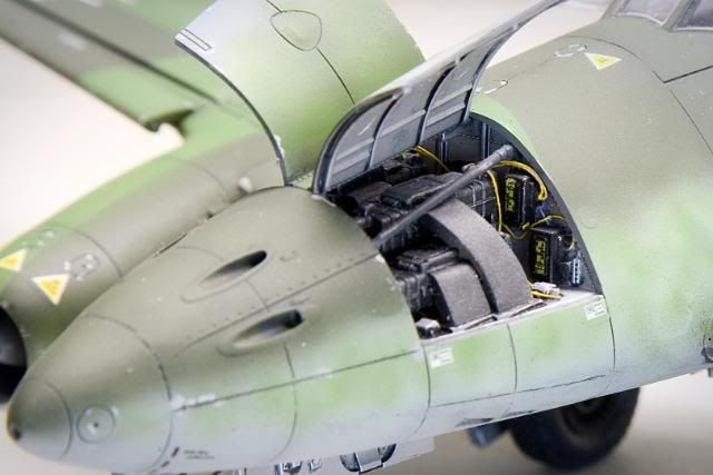
Next I decided to work on the resin engine, while I try to figure out what brand of paint I'm going to use for the RLM colors. I still may mix them from Tamiya just for use comfort sake.
I must say this was the most difficult resin piece I have ever done. Lack of instruction for allignment, and the fact that there are three major resin pieces that are round and need to be sanded flat on the matting surfaces, drove me nuts.
I used sanding sticks, sand paper on glass, you name it. It was one issue after another. I finally settled before I sanded them all the way down to 1mm disks. Here are the results. 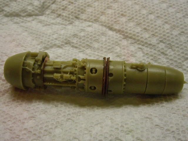


I added some more wires to try and match the reference photos without going to crazy.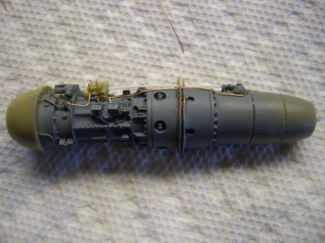
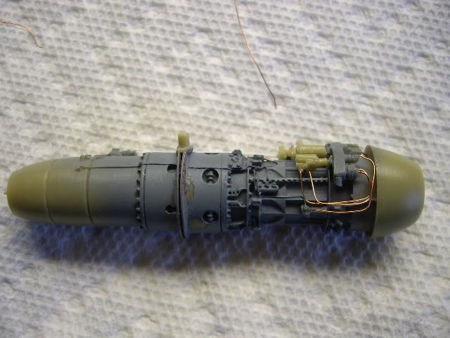
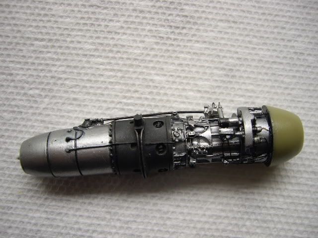
I chose to use Citadel for the main aluminum color, and Tamiya Nato black for the center. Looking at the photos I found a jet exhaust color matched the gold looking parts.
There really wasn't much to paint, which was disapointing. I had to keep myself from painting all the little boxes on the engine black as the photos show they were all silver.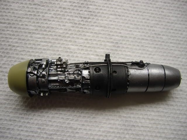
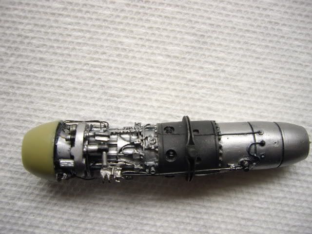

I applied a quick wash and didn't wipe that much off. I may go back later and "heat" the back end of the engine up a bit, but not sure.
The next thing I got on with is the mounting of the slats and flaps. I thinned out the underside of the kit surfaces, as they looked a little thick. 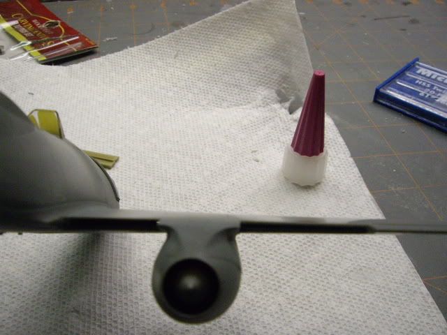

Finished...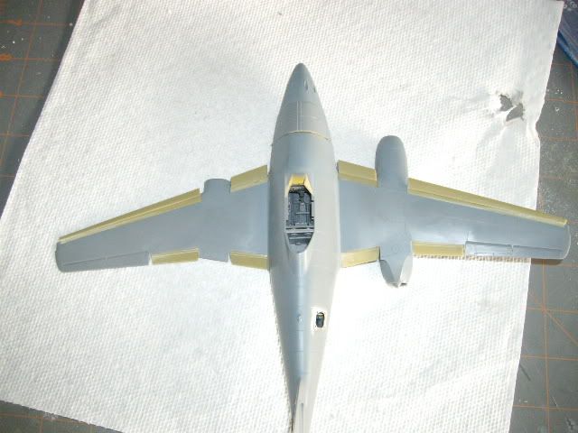
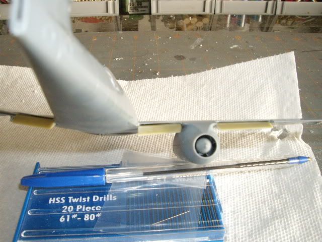
Next I noticed they didn't mold the control rods for the trim tabs on the elevators...so I streached some sprue and on they went.
I probably should have waited for this because of the masking and such, but they held up....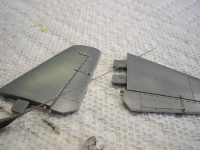
This time I remembered to put the wing lamps on before I finished so I could sand them in. Tamiya does a nice job with these and puts a little hole in them for you to paint the bulb.
Problem is I'm prone to loosing this stuff and one pinged off the tweezers. Another thirty minutes on the floor and I gave up. I wound up using the clear light section for the kit rudder.
This part is unused on the variant I'm doing so it worked out ok, just a little more sanding....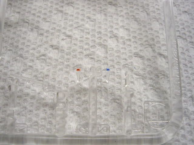
Next I taped and primed.....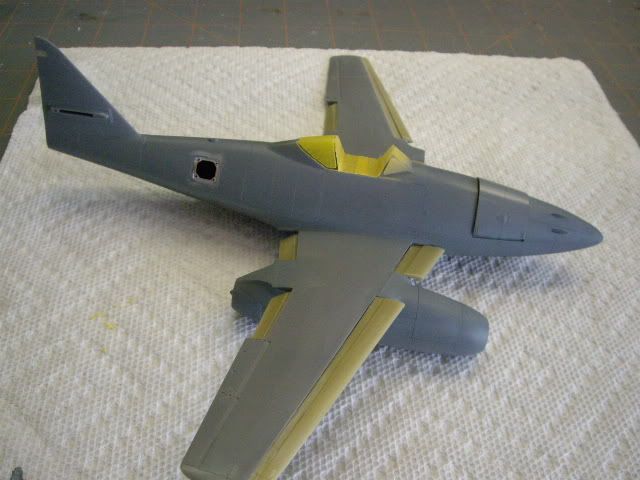
On to the paint stage. I had RLM 76 82 83 in Model Master Enamels but didn't want to use them. I sprayed the MM on a scrap to try and match the colors using Tamiya. 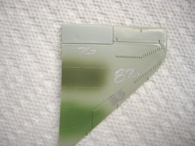
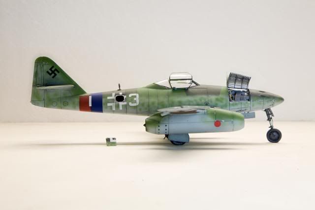
I wound up finding the colors in the PolyScale line. This was the results...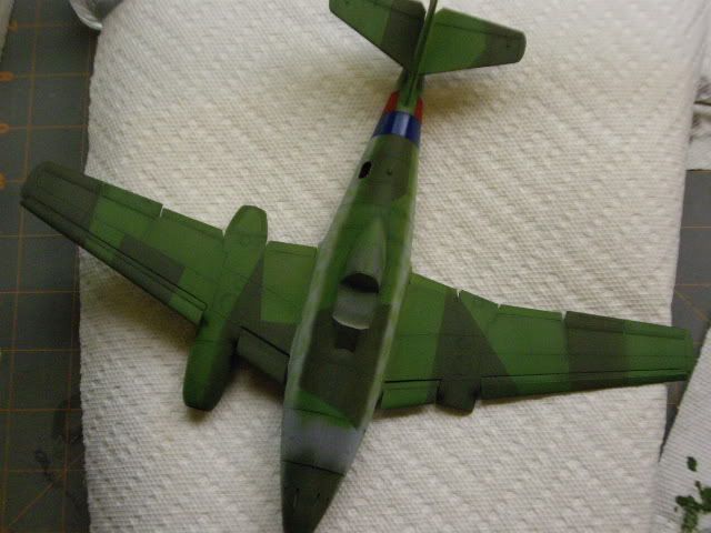

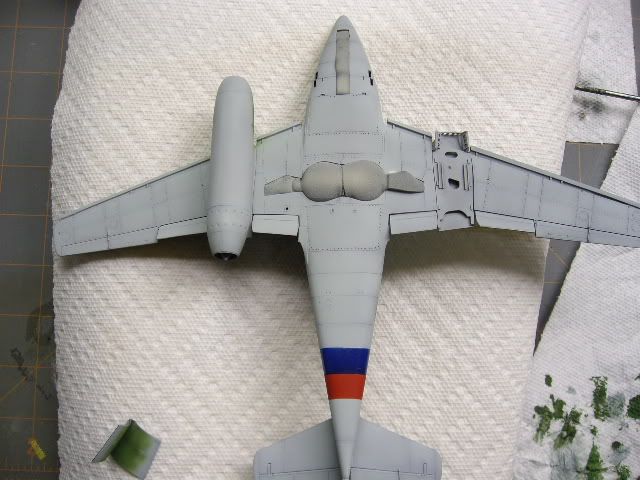
While I had the airbrush going I decided to mask up the red and blue bands at the back instead of using the decals....Glad I did this....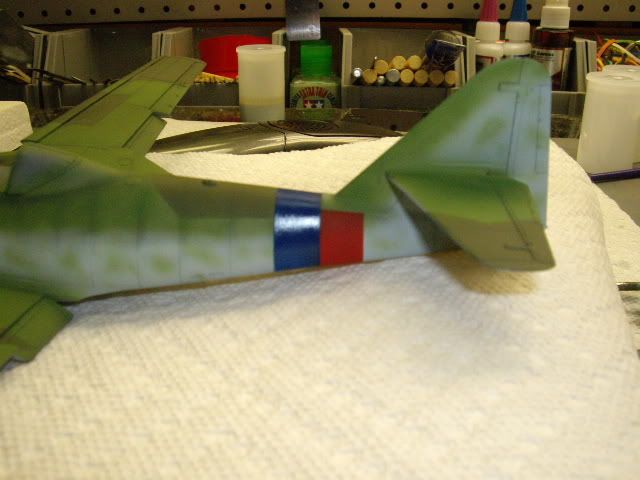
As for the Motteling this was my first attempt at it. I'm not too happy with it but I decided to stop where it is. I can add more later after I step back. I now know why I avoided doing this kit.
Part of the problem was the Polyscale paint. If is a step above Testors Acryl, but is very similar. I didn't like how it sprayed and it was constant cleaning and fiddling. So a combination of a new paint and a skill I don't have resulted in the above.
Anyways, now it's on to the home streach, I hope.
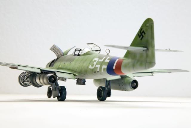
Well almost done. I have to add some antenae and the gun sight but for the most part it's done....Heres the last part of the progress.....
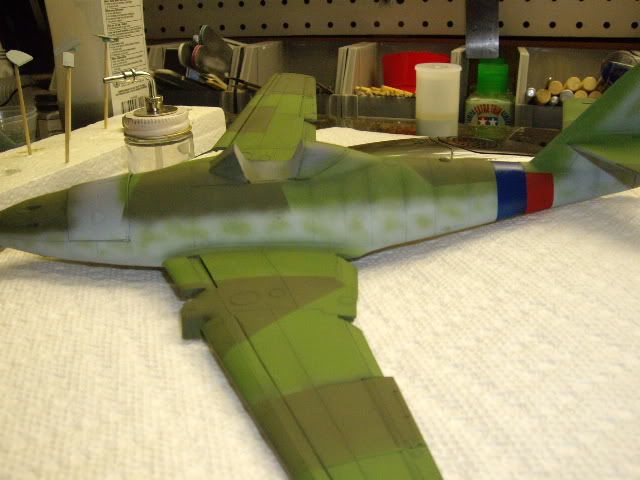
I added some more mottleing to the sides...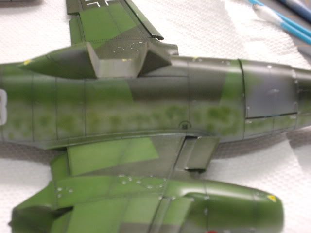

Added the decals....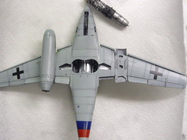


Used Phils wash and used a silver Sharpie pen to chip some paint....I hit the slats pretty hard as they were bent easily and had to be re-shaped by the ground crews a lot. 

Here I fixed all the things I should have left off in the first place. I broke the retract piston and had to make a new ball joint socket and piston out of brass rod. I added some brake line too.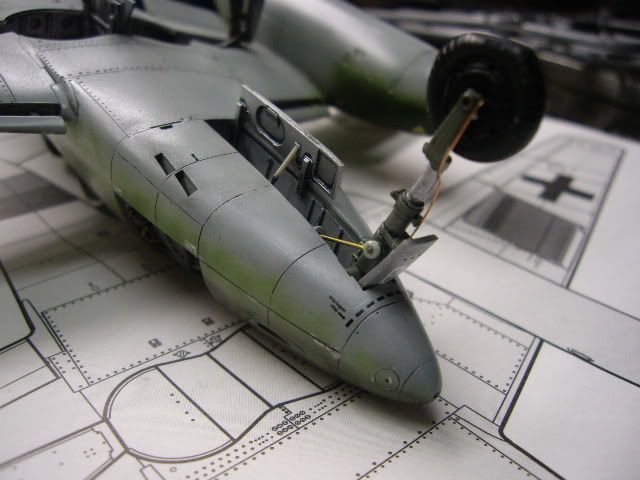
Here is an important tid bit for this kit...Make sure you put the mail wheel retract pistons in place first. Kit parts B2.
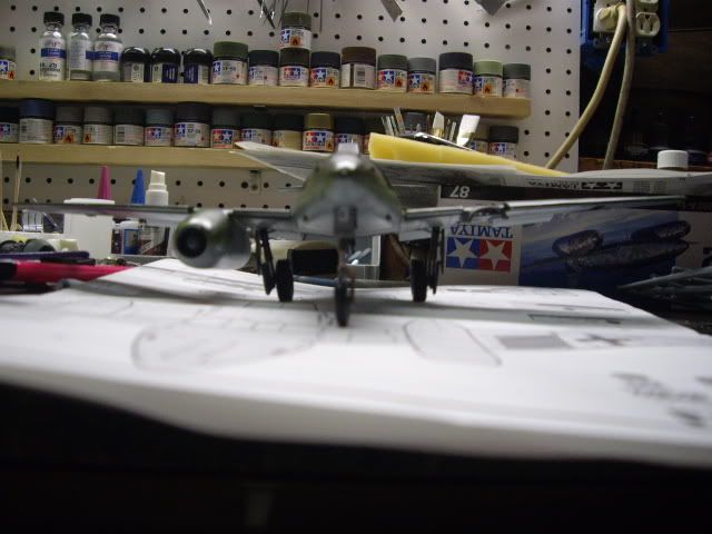
Checking the main gear angles.....The resin wheels are ok. they attempted to shape the wheels to simulate the angled tread wear, but only did one side?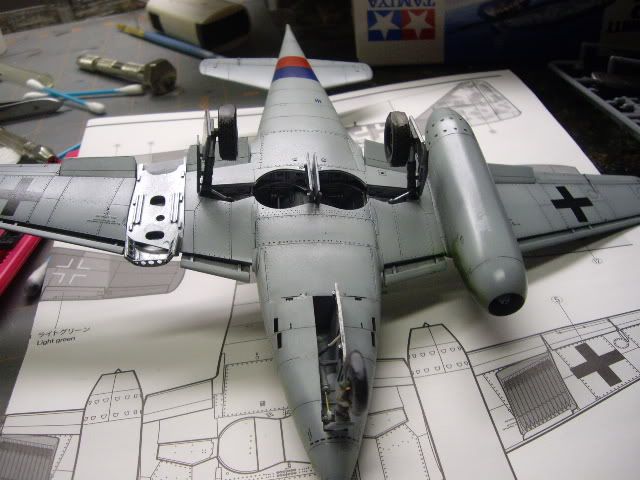
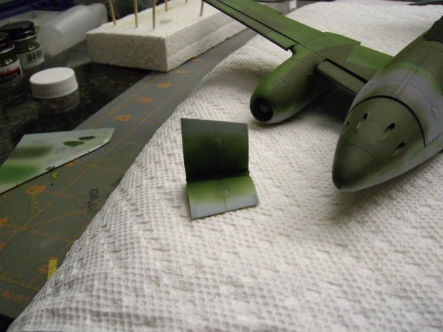
Painted the little PE access cover for the radio compartment. I had to mottle this too. 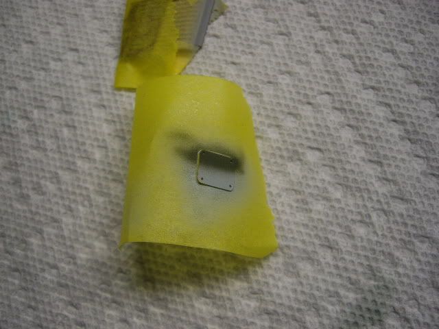
Painted up the rocket pads under the wings. I decided to leave the rockets off. I figured if the plane was undergoing maintenance, it wouldn't be armed.
The lines in the middle of the tape next to the toothpick are a result of that. The paint was thick enough to cover the pads in one pass, yet it was smooth enough to get down this fine at 20 psi. 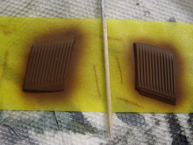
Final reveal pictures